Noise mask of magnetic field strength for the inverted full-disk vector magnetic field data
Noise mask of magnetic field strength is a full-disk map that represents
the noise of magnetic field strength over the Sun's disk.
1. Generate noise mask
Noise mask is derived from a group of FD10 full-disk magnetic field strength data. It has been
demonstrated that the noise of field strength varies over the Sun's disk, and the noise pattern
also changes with the orbital velocity (Vr). Thus it is necessary to generate Vr-dependent noise
masks. The method is described in below.
First, the field strength data are selected by the orbital velocity Vr. For example, for velocity
Vr_center, the selected data have a velocity in [Vr_center - delta_Vr, Vr_center + delta_Vr].
Currently delta_Vr = 50. Usually there are 51 data sets in each Vr bin. Second, the median of
the field strength for each on-disk pixel is calculated from the selected data. Strong field
pixels where field > 300.0 Gauss, roughly 3 sigma of field noise, are excluded. Finally, a 15-order
2D polynomial is performed to fit the median. The polynomial is the Chebyshev polynomials of the
first kind. The fitted polynomial is the noise mask for Vr_center. The coefficients of the polynomials,
which are used to reconstruct the noise mask, are archived in JSOC with a series name of
su_yang.lookup_ChebyCoef_TWindow. The prime keys are Vr, the orbital velocity, and MASKID, the mask
id that denotes time interval in which the noise mask is applied. Currently, the archived coefficients have
a range of Vr = [-3600 m/s, 3600 m/s] with a step of 100 m/s. The mask id, MASKID, is [0, 4], that
denotes certain time period described in below. Examples of noise mask are shown
in
Fig. 1.
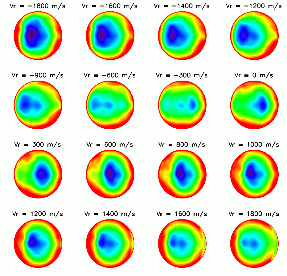
Fig. 1: Derived noise masks for a range of orbital velocites, Vr.
2. Noise mask and change of instrument
Change of instrument setting took place at several instants (see the list in below). Consequently
the noise appears to change slightly. To reflect such change, the noise masks need to be generated
separately for each time period that has the same settings. The time period is denoted by the prime
key MASKID, as specified in Table 1.
Table 1: Prime key MASKID and the corresponding time period
|
| MASKID |
Time period |
| MASKID = 0 |
2010.04.30_00:00:00_TAI TO 2010.12.13_19:47:00_TAI |
| MASKID = 1 |
2010.12.13_19:47:00_TAI TO 2011.07.13_18:35:00_TAI |
| MASKID = 2 |
2011.07.13_18:35:00_TAI TO 2012.01.18_18:15:00_TAI |
| MASKID = 3 |
2012.01.18_18:15:00_TAI TO 2013.03.14_06:40:00_TAI |
| MASKID = 4 |
2013.03.14_06:40:00_TAI TO 2014.01.15_19:18:00_TAI |
| MASKID = 5 |
2014.01.15_19:18:00_TAI TO 2015.04.08_18:53:00_TAI |
| MASKID = 6 |
2015.04.08_18:53:00_TAI TO 2016.04.27_18:56:00_TAI |
| MASKID = 7 |
2016.04.27_18:56:00_TAI TO 2017.04.19_20:05:00_TAI |
| MASKID = 8 |
2017.04.19_20:05:00_TAI TO 2019.04.23_18:43:00_TAI |
| MASKID = 9 |
2019.04.23_18:43:00_TAI TO 2020.10.21_20:52:00_TAI |
| MASKID = 10 |
2020.10.21_20:52:00_TAI TO PRESENT |
Note: Change of the instrument:
2010.12.13_19:47 Change tuning from 500 to 600
2011.07.13_18:35 Change tuning from 600 to 620
2011.07.13_18:40 Change exposure time from 120ms to 125ms
2012.01.18_18:15 Change tuning from 620 to 640
2013.03.14_06:40
3. Validation of the noise mask
Fig. 2 shows a comparison between observed field strengths (Columns 1 and 3)
and their noise masks (Columns 2 and 4) derived from the Chebyshev polynomials. The coefficients of the polynomials
are obtained by interpolating coefficients of two orbital velocities closest to the velocity of interest. For example,
for a Vr_obs = 1775 m/s data, its coefficients (Vr_obs = 1775) = [1 - (1775-1700)/100] * coefficients (Vr = 1700) + [1 - (1800-1775)/100] * coefficients (Vr = 1800). The noise masks successfully recover the patterns of observed field
strengths. Some of subtle details shown in observation are also reproduced (e.g. the ring-like structure in the
Vr = 1775 m/s data).
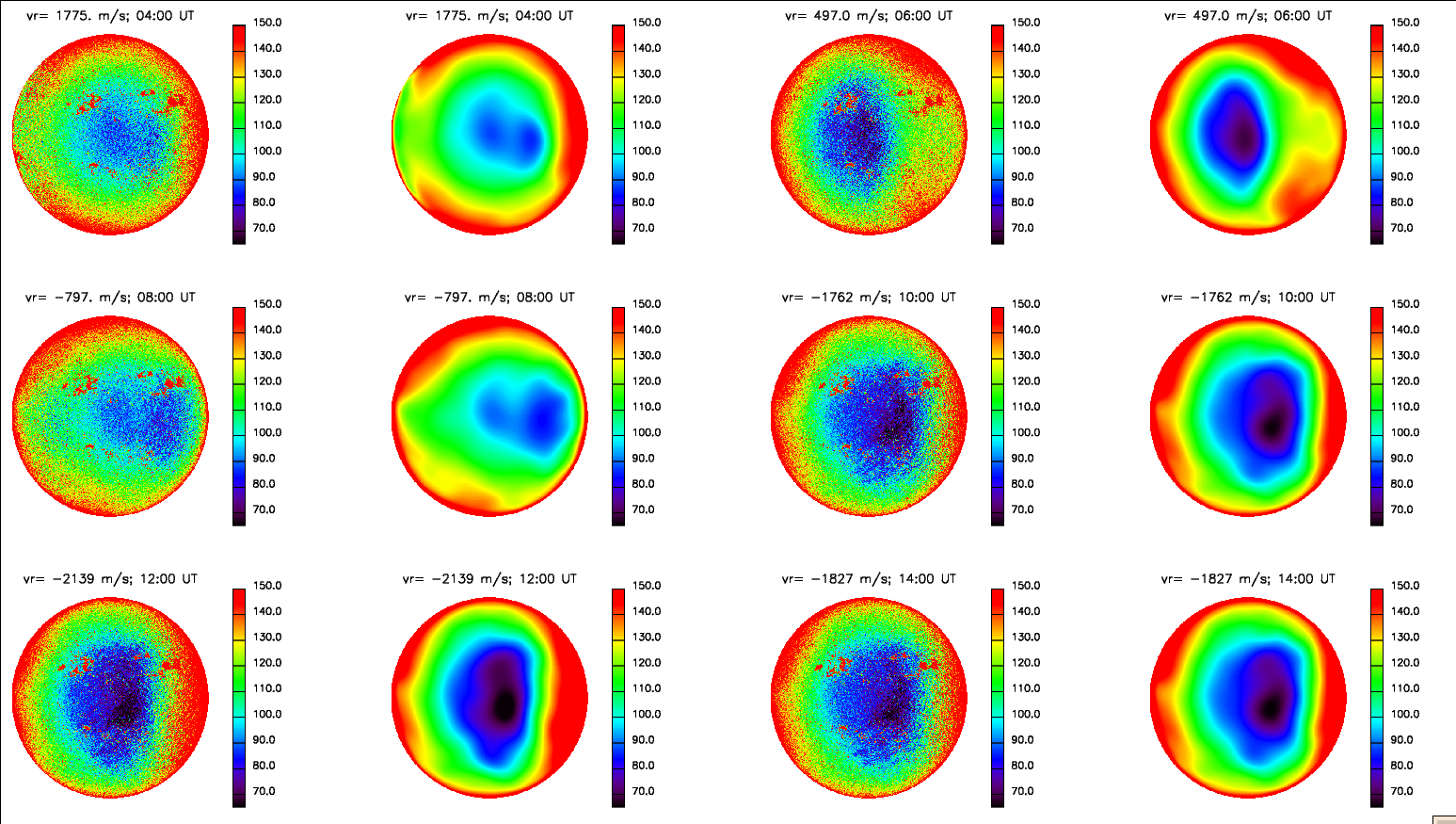
Fig. 2: Comparison between observation and recovered noise mask
Quantitative validation is shown in
Fig. 3. From left to
right are observed field strength (first column), recovered noise mask (second), distribution of
field strength (third), and distribution of difference of field strength and noise mask (fourth).
The red lines in Columns 3 and 4 are Gaussian functions that fit the distributions. The differences
exhibit a gaussian distribution, centered at ~ 0.0 Mx/cm^2.
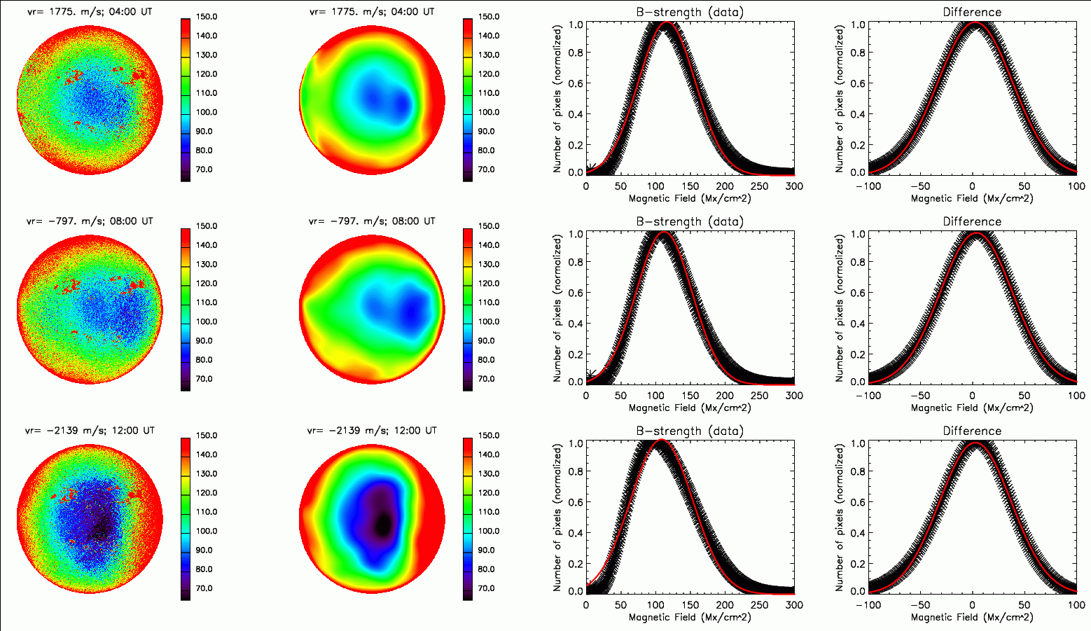
Fig. 3: Quantitative validation between observation and noise mask